Linear circuit elements refer to the components in an electrical circuit that exhibit a linear relationship between the current input and the voltage output. Examples of elements with linear circuits include −
- Resistors
- Capacitors
- Inductors
- Transformers
To get a better understanding of linear circuit elements, an analysis of resistor elements is necessary.
Resistors
A resistor is a device in which the flow of an electric current is restricted resulting in an energy conversion. For example, when electricity flows through a light bulb, the electricity is converted into a different form of energy such as heat and/or light. The resistance of an element is measured in ohms (Ω).
The measure of resistance in a given circuit is given by −
$$R=rho frac{L}{A}$$
Where R − resistance; ρ − resistivity; L − length of wire; and A − cross-sectional area of wire
Symbol of Various Resistors
| Resistor |  |
| A variable resistor |  |
| A potentiometer |  |
Capacitors
A capacitor refers to an electrical device that has two conducting materials (also known as plates) separated by an insulator known as a dielectric. It uses electric field to store electric energy. The electric field is developed when the capacitor is connected to a battery, thus making positive electric charges accumulate on one plate and negative electric charges on the other plate.
When energy is stored in the electrical field of a capacitor, the process is called charging, and when energy is removed, the process is called discharging. The level of electrical energy stored in a capacitor is called capacitance and is measured in farads (F). One farad is the same as one coulomb per unit volt given by 1 C/V.
The difference between a capacitor and a battery is that a capacitor stores electrical energy while a battery stores chemical energy and releases the energy at a slow rate.
Symbol of Various Capacitors
The various symbols of a capacitor are given in the table below.
| Fixed Capacitor |  |
| Variable Capacitor |  |
| Polarized Capacitor |  |
Inductors
Inductors are electronic devices that use magnetic field to store electric energy. The simplest form of an inductor is a coil or a wire in loop form where the inductance is directly proportional to the number of loops in the wire. In addition, the inductance depends on the type of material in the wire and the radius of the loop.
Given a certain number of turns and radius size, only the air core can result in the least inductance. The dielectric materials, which serve the same purpose as air include wood, glass, and plastic. These materials help in the process of winding the inductor. The shape of the windings (donut shape) as well as ferromagnetic substances, for example, iron increase the total inductance.
The amount of energy that an inductor can store is known as inductance. It is measured in Henry (H).
Symbol of Various Inductors
| Fixed inductor |  |
| Variable inductor |  |
Transformers
This refers to a device that alters energy from one level to another through a process known as electromagnetic induction. It is usually used to raise or lower AC voltages in applications utilizing electric power.
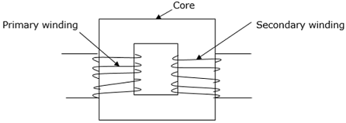
When the current on the primary side of the transformer is varied, a varied magnetic flux is created on its core, which spreads out to the secondary windings of the transformer in form of magnetic fields.
The operation principle of a transformer relies on Faraday’s law of electromagnetic induction. The law states that the rate of change of the flux linking with respect to time is directly related to the EMF induced in a conductor.
A transformer has three main parts −
- Primary winding
- Magnetic core
- Secondary winding

Symbol of a Transformer

Additional Devices
Electromagnetic Devices
The concept of electromagnetism is widely used in technology and it is applied in motors, generators and electric bells. For example, in a doorbell, the electromagnetic component attracts a clapper that hits the bell and causes it to ring.
Controllers
Controllers are devices that receive electronic signals transferred from a measured variable in a process and compare the value obtained with a set point of control. It utilizes digital algorithms to correlate and compare functions.
Sensors
Sensors are used to determine current, which constantly varies to provide feedback for purposes of control. Sensing current makes it possible to achieve a smooth and accurate converter function. Current sensors are critical in converters such that the information in parallel or multiphase converters is easily shared.
Filters
Electronic filters are also used to carry out processing of signals to remove undesired frequencies. They are analog circuits and exist in either active or passive state.
Learning working make money