The earth segment of satellite communication system mainly consists of two earth stations. Those are transmitting earth station and receiving earth station.
The transmitting earth station transmits the information signals to satellite. Whereas, the receiving earth station receives the information signals from satellite. Sometimes, the same earth station can be used for both transmitting and receiving purposes.
In general, earth stations receive the baseband signals in one of the following forms. Voice signals and video signals either in analog form or digital form.
Initially, the analog modulation technique, named FM modulation is used for transmitting both voice and video signals, which are in analog form. Later, digital modulation techniques, namely Frequency Shift Keying (FSK) and Phase Shift Keying (PSK) are used for transmitting those signals. Because, both voice and video signals are used to represent in digital by converting them from analog.
Block Diagram of Earth Station
Designing of an Earth station depends not only on the location of earth station but also on some other factors. The location of earth stations could be on land, on ships in sea and on aircraft. The depending factors are type of service providing, frequency bands utilization, transmitter, receiver and antenna characteristics.
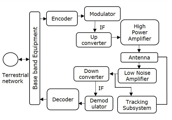
The block diagram of digital earth station is shown in below figure.

We can easily understand the working of earth station from above figure. There are four major subsystems that are present in any earth station. Those are transmitter, receiver, antenna and tracking subsystem.
Transmitter
The binary (digital) information enters at base band equipment of earth station from terrestrial network. Encoder includes error correction bits in order to minimize the bit error rate.
In satellite communication, the Intermediate Frequency (IF) can be chosen as 70 MHz by using a transponder having bandwidth of 36 MHz. Similarly, the IF can also be chosen as 140 MHz by using a transponder having bandwidth of either 54 MHz or 72 MHz.
Up converter performs the frequency conversion of modulated signal to higher frequency. This signal will be amplified by using High power amplifier. The earth station antenna transmits this signal.
Receiver
During reception, the earth station antenna receives downlink signal. This is a low-level modulated RF signal. In general, the received signal will be having less signal strength. So, in order to amplify this signal, Low Noise Amplifier (LNA) is used. Due to this, there is an improvement in Signal to Noise Ratio (SNR) value.
RF signal can be down converted to the Intermediate Frequency (IF) value, which is either 70 or 140 MHz. Because, it is easy to demodulate at these intermediate frequencies.
The function of the decoder is just opposite to that of encoder. So, the decoder produces an error free binary information by removing error correction bits and correcting the bit positions if any.
This binary information is given to base band equipment for further processing and then delivers to terrestrial network.
Earth Station Antenna
The major parts of Earth station Antenna are feed system and Antenna reflector. These two parts combined together radiates or receives electromagnetic waves. Since the feed system obeys reciprocity theorem, the earth station antennas are suitable for both transmitting and receiving electromagnetic waves.
Parabolic reflectors are used as the main antenna in earth stations. The gain of these reflectors is high. They have the ability of focusing a parallel beam into a point at the focus, where the feed system is located.
Tracking Subsystem
The Tracking subsystem keeps track with the satellite and make sure that the beam comes towards it in order to establish the communication. The Tracking system present in the earth station performs mainly two functions. Those are satellite acquisition and tracking of satellite. This tracking can be done in one of the following ways. Those are automatic tracking, manual tracking & program tracking.
Learning working make money