If CW Doppler Radar uses the Frequency Modulation, then that Radar is called FMCW Doppler Radar or simply, FMCW Radar. It is also called Continuous Wave Frequency Modulated Radar or CWFM Radar. It measures not only the speed of the target but also the distance of the target from the Radar.
Block Diagram of FMCW Radar
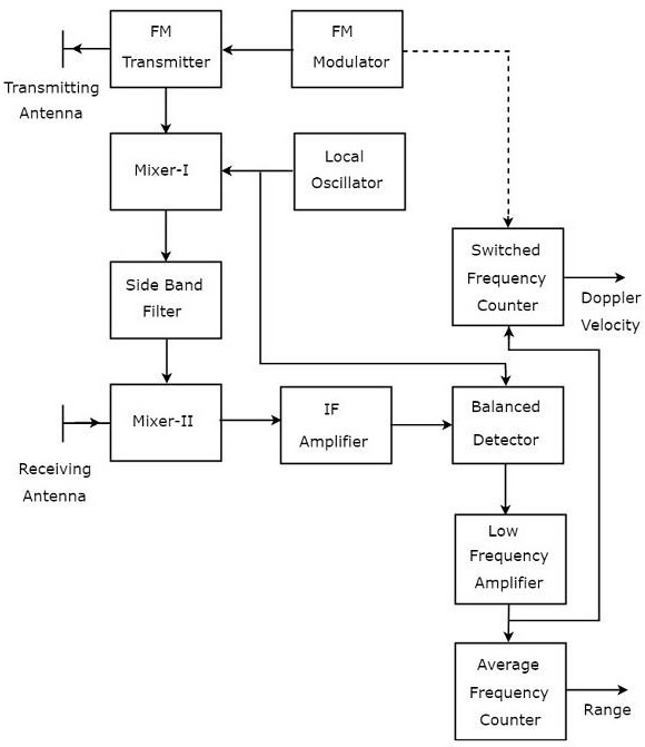
FMCW Radar is mostly used as Radar Altimeter in order to measure the exact height while landing the aircraft. The following figure shows the block diagram of FMCW Radar −

FMCW Radar contains two Antennas − transmitting Antenna and receiving Antenna as shown in the figure. The transmitting Antenna transmits the signal and the receiving Antenna receives the echo signal.
The block diagram of the FMCW Radar looks similar to the block diagram of CW Radar. It contains few modified blocks and some other blocks in addition to the blocks that are present in the block diagram of CW Radar. The function of each block of FMCW Radar is mentioned below.
-
FM Modulator − It produces a Frequency Modulated (FM) signal having variable frequency, $f_oleft (t right )$ and it is applied to the FM transmitter.
-
FM Transmitter − It transmits the FM signal with the help of transmitting Antenna. The output of FM Transmitter is also connected to Mixer-I.
-
Local Oscillator − In general, Local Oscillator is used to produce an RF signal. But, here it is used to produce a signal having an Intermediate Frequency, $f_{IF}$. The output of Local Oscillator is connected to both Mixer-I and Balanced Detector.
-
Mixer-I − Mixer can produce both sum and difference of the frequencies that are applied to it. The signals having frequencies of $f_oleft (t right )$ and $f_{IF}$ are applied to Mixer-I. So, the Mixer-I will produce the output having frequency either $f_oleft (t right )+f_{IF}$ or $f_oleft (t right )-f_{IF}$.
-
Side Band Filter − It allows only one side band frequencies, i.e., either upper side band frequencies or lower side band frequencies. The side band filter shown in the figure produces only lower side band frequency. i.e., $f_oleft (t right )-f_{IF}$.
-
Mixer-II − Mixer can produce both sum and difference of the frequencies that are applied to it. The signals having frequencies of $f_oleft (t right )-f_{IF}$ and $f_oleft (t-T right )$ are applied to Mixer-II. So, the Mixer-II will produce the output having frequency either $f_oleft (t-T right )+f_oleft (t right )-f_{IF}$ or $f_oleft (t-T right )-f_oleft (t right )+f_{IF}$.
-
IF Amplifier − IF amplifier amplifies the Intermediate Frequency (IF) signal. The IF amplifier shown in the figure amplifies the signal having frequency of $f_oleft (t-T right )-f_oleft (t right )+f_{IF}$. This amplified signal is applied as an input to the Balanced detector.
-
Balanced Detector − It is used to produce the output signal having frequency of $f_oleft (t-T right )-f_oleft (t right )$ from the applied two input signals, which are having frequencies of $f_oleft (t-T right )-f_oleft (t right )+f_{IF}$ and $f_{IF}$. The output of Balanced detector is applied as an input to Low Frequency Amplifier.
-
Low Frequency Amplifier − It amplifies the output of Balanced detector to the required level. The output of Low Frequency Amplifier is applied to both switched frequency counter and average frequency counter.
-
Switched Frequency Counter − It is useful for getting the value of Doppler velocity.
-
Average Frequency Counter − It is useful for getting the value of Range.
Learning working make money