Ideal Transformer
An ideal transformer is an imaginary model of the transformer which possesses the following characteristics −
-
The primary and secondary windings have negligible (or zero) resistance.
-
It has no leakage flux, i.e., whole of the flux flows through the magnetic core of the transformer.
-
The magnetic core has infinite permeability, which means it requires negligible MMF to establish flux in the core.
-
There are no losses due winding resistances, hysteresis and eddy currents. Hence, its efficiency is 100 %.
Working of an Ideal Transformer
We may analyze the operation of an ideal transformer either on no-load or on-load, which is discussed in the following sections.
Ideal Transformer on No-Load
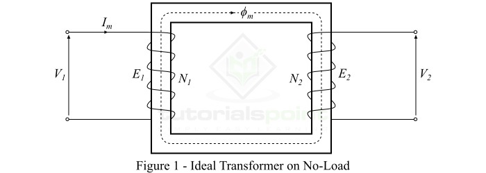
Consider an ideal transformer on no-load, i.e., its secondary winding is open circuited, as shown in Figure-1. And, the primary winding is a coil of pure inductance.

When an alternating voltage $mathit{V_{mathrm{1}}}$ is applied to the primary winding, it draws a very small magnetizing current $mathit{I_{mathit{m}}}$ to establish flux in the core, which lags behind the applied voltage by 90°. The magnetizing current Im produces an alternating flux $mathit{phi_{m}}$ in the core which is proportional to and in phase with it. This alternating flux ($mathit{phi_{m}}$) links the primary and secondary windings magnetically and induces an EMF $mathit{E_{mathrm{1}}}$ in the primary winding and an EMF $mathit{E_{mathrm{2}}}$ in the secondary winding.
The EMF induced in the primary winding $mathit{E_{mathrm{1}}}$ is equal to and opposite of the applied voltage $mathit{V_{mathrm{1}}}$ (according to Lenz’s law). The EMFs $mathit{E_{mathrm{1}}}$ and $mathit{E_{mathrm{2}}}$ lag behind the flux ($mathit{phi_{m}}$) by 90°, however their magnitudes depend upon the number of turns in the primary and secondary windings. Also, the EMFs $mathit{E_{mathrm{1}}}$ and $mathit{E_{mathrm{2}}}$ are in phase with each other, while $mathit{E_{mathrm{1}}}$ is equal to $mathit{V_{mathrm{1}}}$ and 180° out of phase with it.
Ideal Transformer on On-Load
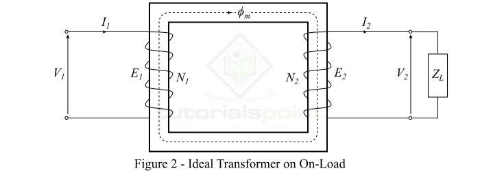
When a load is connected across terminals of the secondary winding of the ideal transformer, the transformer is said to be loaded and a load current flows through the secondary winding and load.

Consider an inductive load of impedance connected across the secondary winding of the ideal transformer as shown in Figure-2. Then, the secondary winding EMF $mathit{E_{mathrm{2}}}$ will cause a current $mathit{I_{mathrm{2}}}$ to flow through the secondary winding and load, which is given by,
$$mathrm{mathit{I_{mathrm{2}}}:=:frac{mathit{E_{mathrm{2}}}}{mathit{Z_{mathit{L}}}}:=:frac{mathit{V_{mathrm{2}}}}{mathit{Z_{mathit{L}}}}}$$
Where, for an ideal transformer, the secondary winding EMF $mathit{E_{mathrm{2}}}$ is equal to the secondary winding terminal voltage $mathit{V_{mathrm{2}}}$.
Since we considered an inductive load, therefore, the current $mathit{I_{mathrm{2}}}$ will lag behind $mathit{E_{mathrm{2}}}$ or $mathit{V_{mathrm{2}}}$ by an angle of $mathit{phi_{mathrm{2}}}$. Also, the no-load current $mathit{I_{mathrm{0}}}$ being neglected because the transformer is ideal one.
The current flowing in the secondary winding ($mathit{I_{mathrm{2}}}$) sets up an MMF ($mathit{I_{mathrm{2}}}mathit{N_{mathrm{2}}}$) which produces a flux $mathit{phi_{mathrm{2}}}$ in opposite direction to the main flux ($mathit{phi_{mathit{m}}}$). As a result, the total flux in the core changes from its original value, however, the flux in the core should not change from its original value. Therefore, to maintain the flux in the core at its original value, the primary current must develop an MMF which can counter-balance the demagnetizing effect of the secondary MMF $mathit{I_{mathrm{2}}}mathit{N_{mathrm{2}}}$.
Hence, the primary current $mathit{I_{mathrm{1}}}$ must flow so that
$$mathrm{mathit{I_{mathrm{1}}}mathit{N_{mathrm{1}}}:=:mathit{I_{mathrm{2}}}mathit{N_{mathrm{2}}}}$$
Therefore, the primary winding must draw enough current to neutralize the demagnetizing effect of the secondary current so that the main flux in the core remains constant. Hence, when the secondary current ($mathit{I_{mathrm{2}}}$) increases, the primary current ($mathit{I_{mathrm{1}}}$) also increases in the same manner and keeps the mutual flux ($mathit{phi_{mathit{m}}}$) constant.
In an ideal transformer on-load, the secondary current $mathit{I_{mathrm{2}}}$ lags behind the secondary terminal voltage $mathit{V_{mathrm{2}}}$ by an angle of $mathit{phi _{mathrm{2}}}$.
Practical Transformer
A practical transformer is one which possesses the following characteristics −
-
The primary and secondary windings have finite resistance.
-
There is a leakage flux, i.e., whole of the flux is not confined to the magnetic core.
-
The magnetic core has finite permeability, hence a considerable amount of MMF is require to establish flux in the core.
-
There are losses in the transformer due to winding resistances, hysteresis and eddy currents. Therefore, the efficiency of a practical transformer is always less than 100 %.
The analytical model of a typical practical transformer is shown in Figure-3.

Characteristics of a Practical Transformer
Following are the important characteristics of a Practical Transformer −
Winding Resistances
The windings of a transformer are usually made up of copper conductors. Therefore, both the primary and secondary windings will have winding resistances, which produce the copper loss or $mathit{i^{mathrm{2}} mathit{R}}$ loss in the transformer. The primary winding resistance $mathit{R_{mathrm{1}}}$ and the secondary winding resistance $mathit{R_{mathrm{2}}}$ act in series with the respective windings as shown in Figure-3.
Iron Losses or Core Losses
The core of the transformer is subjected to the alternating magnetic flux, hence the eddy current loss and hysteresis loss occur in the core. The hysteresis loss and eddy current loss together are known as iron loss or core loss. The iron loss of the transformer depends upon the supply frequency, maximum flux density in the core, volume of the core and thickness of the laminations etc. In a practical transformer, the magnitude of iron loss is practically constant and very small.
Leakage Flux
The current through the primary winding produces a magnetic flux. The flux $mathit{phi _{mathit{m}}}$ which links both primary and secondary windings is the useful flux and is known as mutual flux. However, a fraction of the flux ($mathit{phi _{mathrm{1}}}$) produced by the primary current does not link with the secondary winding.
When a load is connected across the secondary winding, a current flows through it and produces a flux ($mathit{phi _{mathrm{2}}}$), which links only with the secondary winding. Thus, the part of $mathit{phi _{mathrm{1}}}$, and the flux $mathit{phi _{mathrm{2}}}$ that link only their respective winding are known as leakage flux.
The leakage flux has its path through the air which has very high reluctance. Therefore, the effect of primary leakage flux ($mathit{phi _{mathrm{1}}}$) is to introduce an inductive reactance ($ mathit{X_{mathrm{1}}}$) in series with the primary winding. Similarly, the secondary leakage flux ($mathit{phi _{mathrm{2}}}$) introduces an inductive reactance ($ mathit{X_{mathrm{2}}}$) in series with the secondary winding as shown in Figure-3.
However, the leakage flux in a practical transformer is very small (about 5% of $mathit{phi _{m}}$), yet it cannot be ignored. Because the leakage flux paths are through the air, which has very high reluctance. Thus, it requires considerable MMF.
Finite Permeability of Core Material
In general, the practical transformers have a core made up of high grade silicon steel, which has a specific relative permeability ($mathit{mu _{r}}$). Thus, the core saturates at a certain value of magnetic flux density. Therefore, the core of a practical transformer has finite permeability and hence possesses reluctance in the path of magnetic flux.
Learning working make money