In the Earth’s atmosphere, the propagation of wave depends not only on the properties of the wave, but also on environment effects and the layers of earth’s atmosphere. All of these have to be studied in order to form an idea of how a wave propagates in the environment.
Let us look at the frequency spectrum over which the signal transmission or reception takes place. Different types of antennas are manufactured depending upon the frequency range in which they are operated.
Electromagnetic Spectrum
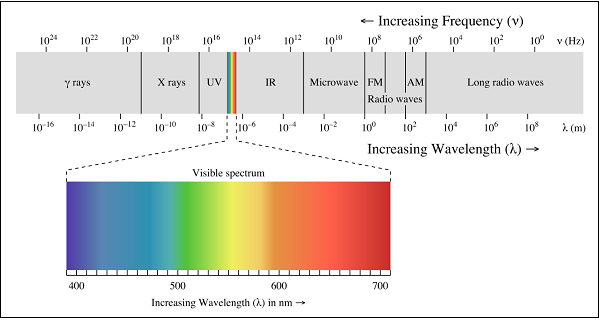
Wireless communication is based on the principle of broadcast and reception of electromagnetic waves. These waves can be characterized by their frequency (f) and their wavelength (λ) lambda.
A pictorial representation of the electromagnetic spectrum is given in the following figure.

Low Frequency bands
Low Frequency bands comprise of the radio, microwave, infrared and visible portions of the spectrum. They can be used for information transmission by modulating the amplitude, frequency or phase of the waves.
High Frequency bands
High Frequency bands comprise of X-rays and Gamma rays. Theoretically, these waves are better for information propagation. However, these waves are not used practically because of difficulty in modulation and the waves are harmful to living beings. In addition, high frequency waves do not propagate well through buildings.
Frequency Bands and their Uses
The following table depicts the frequency bands and its uses −
| Band Name | Frequency | Wavelength | Applications |
|---|---|---|---|
| Extremely Low Frequency (ELF) | 30 Hz to 300 Hz | 10,000 to 1,000 KM | Power line frequencies |
| Voice Frequency (VF) | 300 Hz to 3 KHz | 1,000 to 100 KM | Telephone Communications |
| Very Low Frequency (VLF) | 3 KHz to 30 KHz | 100 to 10 KM | Marine Communications |
| Low Frequency (LF) | 30 KHz to 300 KHz | 10 to 1 KM | Marine Communications |
| Medium Frequency (MF) | 300 KHz to 3 MHz | 1000 to 100 m | AM Broadcasting |
| High Frequency (HF) | 3 MHz to 30 MHz | 100 to 10 m | Long distance aircraft/ship Communications |
| Very High Frequency(VHF) | 30 MHz to 300 MHz | 10 to 1 m | FM Broadcasting |
| Ultra High Frequency (UHF) | 300 MHz to 3 GHz | 100 to 10 cm | Cellular Telephone |
| Super High Frequency (SHF) | 3 GHz to 30 GHz | 10 to 1 cm | Satellite Communications, Microwave links |
| Extremely High Frequency (EHF) | 30 GHz to 300 GHz | 10 to 1 mm | Wireless local loop |
| Infrared | 300 GHz to 400 THz | 1 mm to 770 nm | Consumer Electronics |
| Visible Light | 400 THz to 900 THz | 770 nm to 330 nm | Optical Communications |
Spectrum Allocation
Since the electromagnetic spectrum is a common resource, which is open for access by anyone, several national and international agreements have been drawn regarding the usage of the different frequency bands within the spectrum. The individual national governments allocate spectrum for applications such as AM/FM radio broadcasting, television broadcasting, mobile telephony, military communication, and government usage.
Worldwide, an agency of the International Telecommunications Union Radio Communication (ITU-R) Bureau called World Administrative Radio Conference (WARC) tries to coordinate the spectrum allocation by the various national governments, so that communication devices that can work in multiple countries can be manufactured.
Transmission Limitations
Four types of limitations that affect electromagnetic wave transmissions are −
Attenuation
According to the standard definition, “The decrease in the quality and the strength of the signal is known as attenuation.”
The strength of a signal falls with distance over transmission medium. The extent of attenuation is a function of distance, transmission medium, as well as the frequency of the underlying transmission. Even in free space, with no other impairment, the transmitted signal attenuates over distance, simply because the signal is being spread over a larger and larger area.
Distortion
According to the standard definition, “Any change that alters the basic relation between the frequency components of a signal or the amplitude levels of a signal is known as distortion.”
Distortion of a signal is the process, which causes disturbance to the properties of signal, adding some unwanted components, which affects the quality of the signal. This is usually in FM receiver, where the received signal, sometimes gets completely disturbed giving a buzzing sound as the output.
Dispersion
According to the standard definition, “Dispersion is the phenomenon, in which the velocity of propagation of an Electromagnetic wave is wavelength dependent.”
Dispersion is the phenomenon of spreading of a burst of electromagnetic energy during propagation. It is especially prevalent in wireline transmissions such as an optical fiber. Bursts of data sent in rapid succession tend to merge due to dispersion. The longer the length of the wire, the more severe is the effect of dispersion. The effect of dispersion is to limit the product of R and L. Where ‘R’ is the data rate and ‘L’ is distance.
Noise
According to the standard definition, “Any unwanted form of energy tending to interfere with the proper and easy reception and reproduction of wanted signals is known as Noise.”
The most pervasive form of noise is thermal noise. It is often modeled using an additive Gaussian model. Thermal noise is due to the thermal agitation of electrons and is uniformly distributed across the frequency spectrum.
Other forms of noise include −
-
Inter modulation noise − Caused by signals produced at frequencies that are sums or differences of carrier frequencies.
-
Crosstalk − Interference between two signals.
-
Impulse noise − Irregular pulses of high energy caused by external electromagnetic disturbances. An impulse noise may not have a significant impact on analog data. However, it has a noticeable effect on digital data, causing burst errors.
Learning working make money