For the generation and amplification of Microwaves, there is a need of some special tubes called as Microwave tubes. Of them all, Klystron is an important one.
The essential elements of Klystron are electron beams and cavity resonators. Electron beams are produced from a source and the cavity klystrons are employed to amplify the signals. A collector is present at the end to collect the electrons. The whole set up is as shown in the following figure.
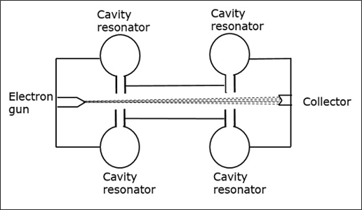
The electrons emitted by the cathode are accelerated towards the first resonator. The collector at the end is at the same potential as the resonator. Hence, usually the electrons have a constant speed in the gap between the cavity resonators.
Initially, the first cavity resonator is supplied with a weak high frequency signal, which has to be amplified. The signal will initiate an electromagnetic field inside the cavity. This signal is passed through a coaxial cable as shown in the following figure.
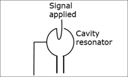
Due to this field, the electrons that pass through the cavity resonator are modulated. On arriving at the second resonator, the electrons are induced with another EMF at the same frequency. This field is strong enough to extract a large signal from the second cavity.
Cavity Resonator
First let us try to understand the constructional details and the working of a cavity resonator. The following figure indicates the cavity resonator.
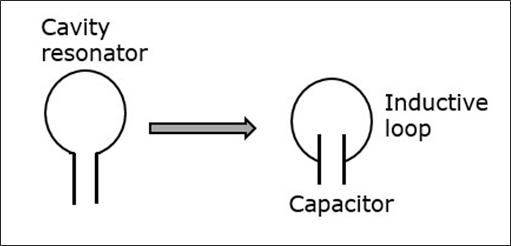
A simple resonant circuit which consists of a capacitor and an inductive loop can be compared with this cavity resonator. A conductor has free electrons. If a charge is applied to the capacitor to get it charged to a voltage of this polarity, many electrons are removed from the upper plate and introduced into the lower plate.
The plate that has more electron deposition will be the cathode and the plate which has lesser number of electrons becomes the anode. The following figure shows the charge deposition on the capacitor.
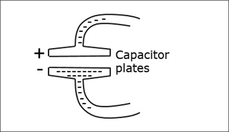
The electric field lines are directed from the positive charge towards the negative. If the capacitor is charged with reverse polarity, then the direction of the field is also reversed. The displacement of electrons in the tube, constitutes an alternating current. This alternating current gives rise to alternating magnetic field, which is out of phase with the electric field of the capacitor.
When the magnetic field is at its maximum strength, the electric field is zero and after a while, the electric field becomes maximum while the magnetic field is at zero. This exchange of strength happens for a cycle.
Closed Resonator
The smaller the value of the capacitor and the inductivity of the loop, the higher will be the oscillation or the resonant frequency. As the inductance of the loop is very small, high frequency can be obtained.
To produce higher frequency signal, the inductance can be further reduced by placing more inductive loops in parallel as shown in the following figure. This results in the formation of a closed resonator having very high frequencies.
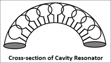
In a closed resonator, the electric and magnetic fields are confined to the interior of the cavity. The first resonator of the cavity is excited by the external signal to be amplified. This signal must have a frequency at which the cavity can resonate. The current in this coaxial cable sets up a magnetic field, by which an electric field originates.
Working of Klystron
To understand the modulation of the electron beam, entering the first cavity, let”s consider the electric field. The electric field on the resonator keeps on changing its direction of the induced field. Depending on this, the electrons coming out of the electron gun, get their pace controlled.
As the electrons are negatively charged, they are accelerated if moved opposite to the direction of the electric field. Also, if the electrons move in the same direction of the electric field, they get decelerated. This electric field keeps on changing, therefore the electrons are accelerated and decelerated depending upon the change of the field. The following figure indicates the electron flow when the field is in the opposite direction.
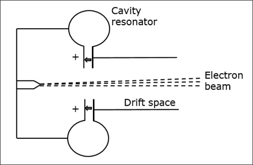
While moving, these electrons enter the field free space called as the drift space between the resonators with varying speeds, which create electron bunches. These bunches are created due to the variation in the speed of travel.
These bunches enter the second resonator, with a frequency corresponding to the frequency at which the first resonator oscillates. As all the cavity resonators are identical, the movement of electrons makes the second resonator to oscillate. The following figure shows the formation of electron bunches.
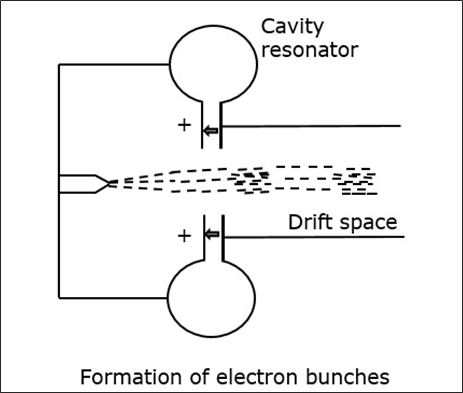
The induced magnetic field in the second resonator induces some current in the coaxial cable, initiating the output signal. The kinetic energy of the electrons in the second cavity is almost equal to the ones in the first cavity and so no energy is taken from the cavity.
The electrons while passing through the second cavity, few of them are accelerated while bunches of electrons are decelerated. Hence, all the kinetic energy is converted into electromagnetic energy to produce the output signal.
Amplification of such two-cavity Klystron is low and hence multi-cavity Klystrons are used.
The following figure depicts an example of multi-cavity Klystron amplifier.
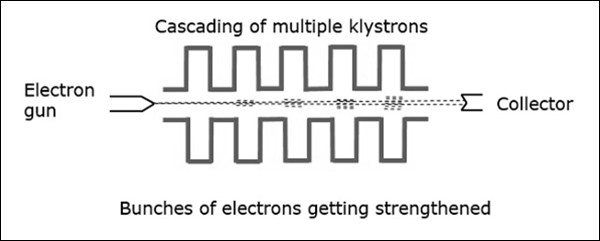
With the signal applied in the first cavity, we get weak bunches in the second cavity. These will set up a field in the third cavity, which produces more concentrated bunches and so on. Hence, the amplification is larger.
Learning working make money